English
 English
 Español
 Português
 русский
 français
 日本語
日本語 Deutsch
 Tiếng Việt
 Italiano
 Nederlands
 ไทย
ไทย Polski
 한국어
한국어 Svenska
 magyar
 Malay
Malay বাংলা
বাংলা Dansk
Dansk Suomi
Suomi हिन्दी
 Pilipino
 Türk
Türk Gaeilge
 عربى
عربى Indonesia
 norsk
norsk اردو
اردو čeština
 Ελληνικά
 Українська
 Javanese
 فارسی
فارسی தமிழ்
தமிழ் తెలుగు
 नेपाली
 Burmese
 български
 ລາວ
ລາວ Latine
 Қазақ
Қазақ Euskal
 Azərbaycan
 slovenský
 Македонски
 Lietuvos
 Eesti Keel
 Română
 Slovenski
 मराठी
मराठी Српски
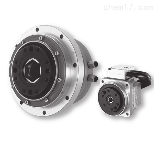
Harmonic Drive servo component FHA-11C-30-E200-C
Harmonic Drive servo component FHA-11C-30-E200-C is an engine used in servo systems to control the operation of mechanical components. It serves as an auxiliary motor with an indirect variable speed mechanism. Servo motors enable precise control over speed and positional accuracy, converting voltage signals into torque and rotational speed to drive controlled objects.
Servo motors are classified into two main types: DC and AC servo motors. Their key characteristic is that they do not rotate on their own when no voltage signal is applied, and their rotational speed decreases uniformly with increasing torque load.
Product Description
SHA series
Abstract
The Harmonic Drive servo component FHA-11C-30-E200-C is a device used in servo systems to control the operation of mechanical components. It serves as an auxiliary motor with an indirect variable speed mechanism. Servo motors enable precise control over speed and positional accuracy, converting voltage signals into torque and rotational speed to drive controlled objects.
In typical control systems, the step response is a key indicator used to evaluate the speed and accuracy of the system's response. It includes several parameters:
- Overshoot : Measures the approximate standard of system stability.
- Rise Time : Time taken for the maximum overshoot to occur.
- Settling Time : Time required for the response to settle within a specified percentage (typically ±2% or ±5%) of the steady-state value.
- Half-peak Time : Time taken for the response to rise from 10% to 90% of the steady-state value.
- Steady-state Error : Error in the output response when it reaches a steady state.
Frequency response analysis evaluates how well the system tracks a sinusoidal input signal. Parameters include:
- Resonance Peak of Frequency Response : Maximum peak amplitude of the output response.
- Resonance Frequency : Frequency at which the resonance peak occurs.
- Bandwidth : Frequency at which the output frequency response decreases to half of its maximum value.
Pneumatic servo mechanisms, using compressed gases as working fluids, are suitable for high-power control systems. However, due to the compressibility of gases, they are not ideal for high-speed responses. Nevertheless, gas leaks are manageable, and the low cost of gas makes them widely used in general factory applications.
In summary, servo mechanisms are designed to track and control systems accurately. Performance evaluation considers both the system's ability to respond rapidly to changes in input (step response) and its ability to track sinusoidal input variations (frequency response).
Specialties
HarmonicDrive ® Integrated AC servo actuator with specially designed flat AC servo motor
Hollow and flat structure
Absolute value encoder
SHA-SG: Compact shape with extra length
SHA-CG: For turntable use, improve the accuracy of output shaft surface vibration

1. Model name: AC servo actuator SHA series
2. Model:
SG type=20, 25, 32, 40, 45, 58, 65
HP type=25,32
CG type=20,25,32,40
3. Version symbols
4. HarmonicDrive ® Reduction ratio:
SG type=51,81101121161
HP type=11
CG type=50,80100120160
5. Type of reducer:
SG type=SHG series
HP type=HPF series
CG type=CSG series
6. Motor version symbol:
A=Models 58, 65
B=Models 25, 32, 40
C=Model 20
D=Model 45
7. Motor size:
● 08=Model 20
09=Model 25
12=Model 32
15=Model 40
16=Model 45
21=Models 58, 65
8. Brake:
● A=No brake
● B=With brake
9. Motor power supply voltage:
100=AC100V
200=AC200V
10. Encoder format:
10=symbol A format, transmission speed: 2.5Mbps, 1:1 connection
11. Encoder type and resolution:
S17b=17bit absolute encoder 131072 pulses/rotation
12. Encoder phase angle:
The phase difference A between the U-phase induced voltage of the motor and the absolute origin is 0 degrees
13 connector specifications:
● C=With standard connectors
● N=No connector
D=With special connectors
14. Optional symbols:
L=Near Origin&End Limit Sensor
Y=Cable side exit
● V=With bracket (CG type only)
● S=Output shaft 1 rotation absolute value specification (CG type only)
● No entry=standard product
SP=non-standard product


