English
 English
 Español
 Português
 русский
 français
 日本語
日本語 Deutsch
 Tiếng Việt
 Italiano
 Nederlands
 ไทย
ไทย Polski
 한국어
한국어 Svenska
 magyar
 Malay
Malay বাংলা
বাংলা Dansk
Dansk Suomi
Suomi हिन्दी
 Pilipino
 Türk
Türk Gaeilge
 عربى
عربى Indonesia
 norsk
norsk اردو
اردو čeština
 Ελληνικά
 Українська
 Javanese
 فارسی
فارسی தமிழ்
தமிழ் తెలుగు
 नेपाली
 Burmese
 български
 ລາວ
ລາວ Latine
 Қазақ
Қазақ Euskal
 Azərbaycan
 slovenský
 Македонски
 Lietuvos
 Eesti Keel
 Română
 Slovenski
 मराठी
मराठी Српски


Harmonic Drive FHA-8C-100-E200-C
The Harmonic Drive FHA-8C-100-E200-C micro workbench harmonic drive can generate radial elastic deformation with an external-toothed flexible wheel, and includes a wave generator installed inside the flexible wheel, elliptical in shape with a flexible roller bearing on the outer ring.
Product Description
SHA series
Abstract
The workbench that moves longitudinally and transversely generally comes equipped with a coordinate device. Commonly used methods for adjusting positions include manual adjustment with graduated handwheels. With increasing demands for machining precision, optical coordinate reading devices, digital readout magnetic scales, and other devices are more frequently employed.
In recent years, with advancements in technology and the development of CNC (Computer Numerical Control) capabilities in machines like the Harmonic Drive FHA-8C-100-E200-C, there have been developments in three-coordinate servo-controlled and five-coordinate CNC EDM (Electrical Discharge Machining) machines. These machines can control spindle and worktable rotation movements along with three-axis servo control. Some machines also feature automatic tool electrode changers.
The spindle head is a critical component in EDM machines, serving as the actuating mechanism in automatic adjustment systems. Its requirements include a simple structure, short transmission chain, minimal transmission clearance, low thermal deformation, sufficient precision, and stiffness to accommodate the demands of automatic adjustment systems. The spindle head primarily consists of feed systems, anti-twist guiding mechanisms, electrode clamping, and adjustment components. Common types of spindle heads used with the Harmonic Drive FHA-8C-100-E200-C include electro-hydraulic and electro-mechanical types.
Electro-hydraulic spindle heads typically come in two structures: one with a fixed hydraulic cylinder where the piston moves with the spindle vertically, and another where the piston is fixed and the hydraulic cylinder body moves with the spindle vertically. The former has a simple structure but lower rigidity, with sliding friction in the spindle guiding parts leading to reduced sensitivity.
Specialties
HarmonicDrive ® Integrated AC servo actuator with specially designed flat AC servo motor
Hollow and flat structure
Absolute value encoder
SHA-SG: Compact shape with extra length
SHA-CG: For turntable use, improve the accuracy of output shaft surface vibration
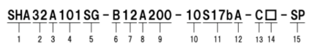
1. Model name: AC servo actuator SHA series
2. Model:
SG type=20, 25, 32, 40, 45, 58, 65
HP type=25,32
CG type=20,25,32,40
3. Version symbols
4. HarmonicDrive ® Reduction ratio:
SG type=51,81101121161
HP type=11
CG type=50,80100120160
5. Type of reducer:
SG type=SHG series
HP type=HPF series
CG type=CSG series
6. Motor version symbol:
A=Models 58, 65
B=Models 25, 32, 40
C=Model 20
D=Model 45
7. Motor size:
● 08=Model 20
09=Model 25
12=Model 32
15=Model 40
16=Model 45
21=Models 58, 65
8. Brake:
● A=No brake
● B=With brake
9. Motor power supply voltage:
100=AC100V
200=AC200V
10. Encoder format:
10=symbol A format, transmission speed: 2.5Mbps, 1:1 connection
11. Encoder type and resolution:
S17b=17bit absolute encoder 131072 pulses/rotation
12. Encoder phase angle:
The phase difference A between the U-phase induced voltage of the motor and the absolute origin is 0 degrees
13 connector specifications:
● C=With standard connectors
● N=No connector
D=With special connectors
14. Optional symbols:
L=Near Origin&End Limit Sensor
Y=Cable side exit
● V=With bracket (CG type only)
● S=Output shaft 1 rotation absolute value specification (CG type only)
● No entry=standard product
SP=non-standard product
